Instman field – The CVCTS steam generator
CHARACTERISTICS
The CVCTS steam generator is built in accordance with the UNE EN12952 Standard, its construction and design being received and reviewed by a Notified Control Body with the “CE” marking, in accordance with Directive 97/23/C.
The CVCTS steam generator is of the water tube type with vertical water tubes, provided with a large radiation-cooled combustion chamber and a symmetrical structure.
The number of tubes and their section are widely dimensioned so as not to offer more than a small pressure loss and, due to the speed of circulation of the water-steam emulsion, the most optimal heat exchange and rapid release of the steam produced.
All the tubes of the bundles can expand without difficulty on their point of union to the collectors and drums to which they are fixed by welding.
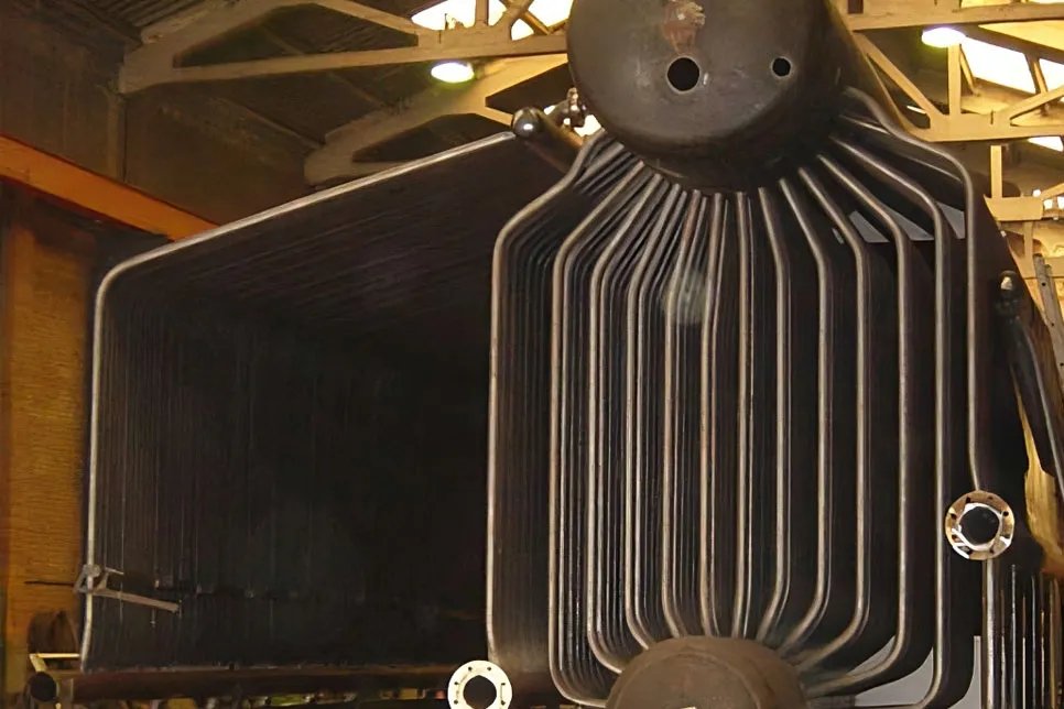
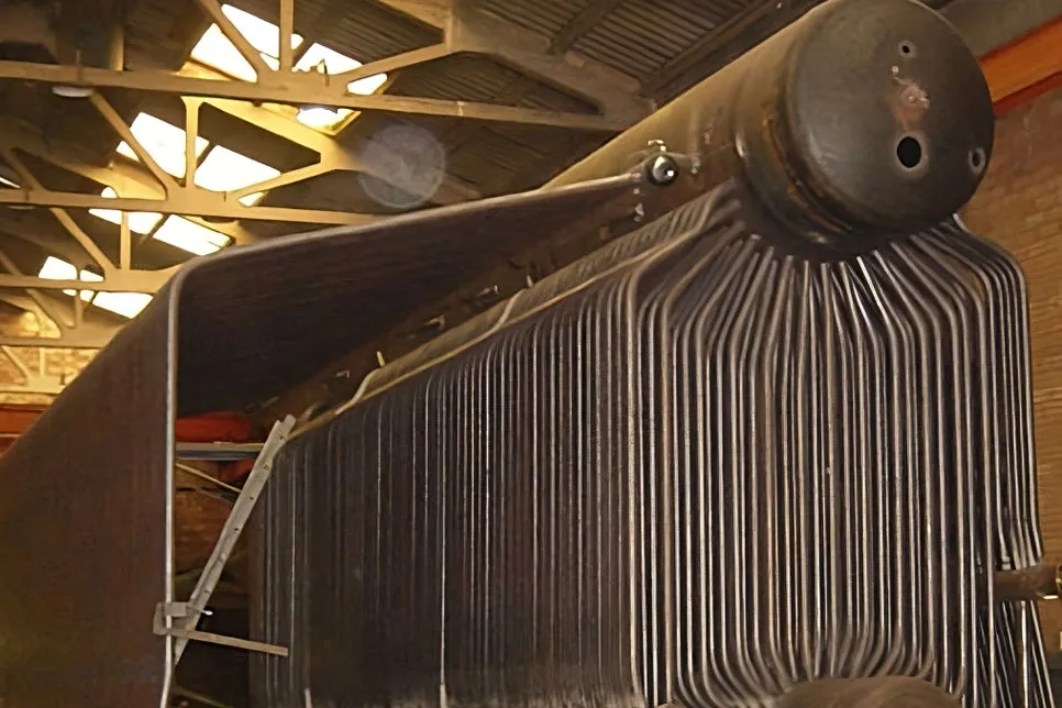
The boiler itself comprises a large-diameter upper water drum, to which the steam formed by the vaporizing bundles and the tubes on the walls that form the combustion chamber arrive.
A special steam separator system allows the production of very dry or saturated steam.
This drum is directly connected to the lower drum, by tubes welded to the bundles, which form the side walls by welded collectors. A settling drum placed in the lower part, like the upper one, has a manhole wide enough to penetrate inside. All the sludge deposited in the lower part of the drum and collectors are evacuated by an extraction valve.
The combustion chamber is formed by the side, front, rear and roof walls, which are cooled by water tubes.
The route of each one of the tubes is established in such a way that a rapid detachment is obtained at the highest point and an emptying at the lowest point.
All tubes subjected to heat are cold bent.
The walls of the combustion chamber and the front and rear are made up of contiguous tubes, without any type of fin/handrail between them, having maximum heat transmission in each of them, consequently cooling the walls, thus extending their useful life.
The tubes of the walls are joined to the collectors by duly approved stuffing and welding.
The heating surface of the generator comprises the combustion chamber as radiation surface and the tubular package between drums as convection surface.
The design of the hearth allows for complete combustion to be carried out in it, so that the temperature of the resulting gases at the entrance of the tube bundle is suitable so that their heat capacity can be used in a highly efficient way.
The special circuit that the fumes carry out in the convection section located between the two main collectors makes the generator’s performance very high, thus achieving highly efficient homogeneous vaporization.
Given the speed of the gases through the tube bundle and its normal direction to the circulation of the water inside it, the caloric use of the fumes is maximum, thus achieving:
- High performance.
- Reduced dimensions.
- Reduced dimensions.
- Uniform distribution of temperatures.